|
Feature Changing protocol
|


The industry has significant motivation to advance the use of this
technology. Compared with traditional techniques, it is anticipated that
computer control will cut the cost of earthmoving by as much as 50 percent. The
technology reduces the amount of work and skills needed by equipment operators,
it eliminates conversion of 2-D construction plans into constructible formats,
and it minimizes survey stake-out. Such benefits to the construction process
also come with changes to the traditional business practices of the project
team, including the engineering and surveying firms, the developers, and, of
course, the contractors themselves.
Effects on business
As engineering firms get involved with this technology, their design data
is being requested for construction purposes. Engineering firms interested in
providing this data have several considerations:
- Who owns the project data? If the engineering firm owns the data, then it has many options for how to handle it. A strong business model would dictate leveraging this data into a profitable commodity, rather than giving it away and hiding it behind waivers.
- Does the company produce construction plans, or does it produce plans that will pass state, county, or local review? While a design-build organization has built-in motivation to develop a set of plans that will both be approvable and constructible, a design firm usually develops plans intended to secure approval by local reviewers. If the firm produces the latter (review plans), is the approved design actually constructible? Would a contractor agree? Designers might be surprised by the answer.
- If a firm produces construction plans, does its design workflow coincide with its ability to deliver the 3-D design data?
- If the company can produce 3-D design data, can it produce it in a way that is usable directly by the contractor?
- If there is liability involved, how should it be handled?
Many contracts that design firms undertake now stipulate that CAD drawings
will be part of the deliverables. Most firms have adjusted to this aspect of
digital transfer. Therefore, firms must decide, on a fundamental level, whether
or not it can back up its drawings with actual and pertinent design data. The
good news is that — so far — the request for digital design data mainly has
been for planned surface data or the proposed DTM. The contractor requires this
information in 3-D and, typically, wants it to be more precise than simple
contours and spot shots. But don’t rest too comfortably; it won’t be long
before 3-D utility data, and curb and gutter information are requested as well.
The bad news is that many civil engineering companies are significantly behind
other engineering disciplines when it comes to designing in three dimensions.
Mechanical and aerospace engineers routinely work in 3-D, while typical civil
engineers design and draw in 2-D. The owner of one engineering firm recently
stated that his firm would not move into 3-D until the county in which he
worked required it. This indicates that this firm is in the business of
preparing review plans and not construction plans. Unfortunately for its clients,
this company is forcing them to incur an unneeded cost to convert approved
plans into 3-D construction plans. One wonders how long developers will absorb
such costs before seeking a more progressive design firm.
Similarly, contractors receive the majority of their budget to build a project, and they usually invest heavily in capital expenditures. Therefore, they are motivated strongly to endorse this technology, which marks somewhat of a turning point in the industry. In fact, contractors may drive design firms to “re-engineer” their design methods so that they can work in a method conducive to delivering the data needed to build sites more effectively.
Effects on client retention
So what happens if an engineering firm declines to provide the requested
data, and the contractor has only the plans in hardcopy or 2-D CAD drawings?
Either the site will be staked-out traditionally by surveyors, or the plans
will be converted from 2-D to 3-D and then into machine-control format.
If the first alternative occurs, the investment made by the contractor is
negated, driving up the project’s costs. If the second scenario happens,
significant fees will be incurred in the conversion process.
In either case, it won’t take long before the developer/client begins to wonder
if he or she is working with an engineering firm that is current with emerging
industry technologies. The parties involved have made six-figure investments
and to achieve a return on them, they need their project teams to work together
closely. If this can’t be accomplished, don’t be surprised if a new team is
assembled on the next project!

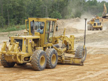
During reconstruction of Texas
state highway 287, contractor T.J. Lambrecht Construction of Euless, Texas,
employed a laser-transmitting robotic total station to track and send plan data
directly to a Topcon 3D-LPS control system on board a motorgrader. Grading
accuracies of 3 to 5 millimeters are obtained with this system.
Effects on revenue
Computer control affects revenue in several ways. One is the loss of
opportunities to survey departments, since stake-out is not required on large
projects when this technology is applied. Because many firms derive a
significant revenue stream from stake-out tasks, firm leaders must refocus
their efforts or risk losing this revenue.
Survey departments’ income can be augmented by developing a quality-control
process to check the newly evolved design data and by beginning to generate
machine-control-formatted data from their own project files. This data could
then be checked for accuracy, integrity, and congruence with the intended
design data.
Another effect is the potential increase in design departments’ revenue. The design staff might begin to prepare their data in such a way that it is conducive for use with machine control. Or, equally likely, they might develop a new revenue stream by converting their DTM data, currently depicted as contours on review plans, into datasets for construction.

The above image is a 3-D
rendering of a TIN for an Alaskan highway. As you can see, major advantages of
developing accurate TINs include enhanced visualization of sites, as well as
the benefit to contractors using machine control.
Effects on design and deliverables
In considering the influence of machine control on design and deliverables,
engineering firms’ design processes will be impacted the most as their methods
evolve. As a technology consultant for engineering and surveying firms, I am
asked frequently about how a company can position itself to provide the
requested data. The reality is that most firms cannot provide the data because
their design workflow is insufficient.
For example, the surface data most firms prepare is intended for reviewers, and
it consists of contours with some spot shots for the locations that the
designers or reviewers feel are pertinent. The judgments made to develop these
contours are depicted on butter paper or on some heavily erased, red-lined
drawing left in a bin somewhere. As you can imagine, these drawings are
inappropriate to give to anyone — no less a contractor for construction
purposes.
A proposed surface needs to be designed in 3-D using a variety of modern tools
and data types. Most of the common CADD software manufacturers have developed
the necessary tools — this is not “new technology,” as these tools have been
around for more than a decade. Using these tools improves not only individual
productivity but also the efficiency of the entire construction process. Even
without the advent of machine control, engineers have few excuses not to design
sites in 3-D. Simply stated, firms that work in 3-D are amazed at the excuses from
those who do not.
Even if a proposed surface is designed in 3-D, it needs to be “connected” to
its design intent. Yet, contour data is not beneficial for construction; a
contractor often requires far greater detail to build a site accurately. For
example, the triangulated irregular network (TIN), which is processed from the
combination of breakline data, contour data, and point data that a designer
uses to develop plan contours, is conducive to building a site (assuming the
TIN data is correct and complete).
Therefore, the modern civil designer needs to design in 3-D and to use
available software to produce traditional contours for review purposes.
Additionally, the TIN corresponding to the contours should be maintained as the
connection between these two datasets, increasing the possibility of supplying
the design data for construction.
Modern deliverables should include a CAD drawing, TIN data, and the machine
control equivalent of that data. A CAD drawing depicts a design’s intent using
traditional techniques such as contours and spot shots. Since contours only
show the design where the contour is drawn, interpretation and subsequent
mistakes occur. Therefore, TIN data needs to be delivered along with CAD
drawing files so that the actual design is represented throughout the site. All
of these deliverables should receive proper quality control, and copies should
be kept in case the design is brought into question at a later date.
Effects on liabilities
Many engineers ask questions involving the increased liability undertaken
by providing their data for construction purposes. Firm managers are concerned
about this for several reasons, ranging from inappropriate use of the data to
its misinterpretation. They also may be concerned, with good reason, that their
own data is incorrect or incomplete.
In reality, the question of liability didn’t really arise with the advent of
machine control. Rather, liability has always been an issue, but it has rested
on other people’s shoulders. With machine control, however, engineering firms
may now bear responsibility for digital data and the format of the datasets
that they transfer to contractors.
It wasn’t long ago that many firms resisted sending CAD drawings as
deliverables for many of the same reasons they hesitate to send digital designs
today: Their managers were allowing hasty, last-minute changes to be made on
the hardcopy mylars, and they failed to institute a procedure where the CAD
files would be updated routinely. As a result, to comply with increasing requests
for these files, firms began putting waivers on their drawings or in the
transmitting agreements, stating that the drawings were not the legal record,
that they may contain typographical errors, or that reusing them would be at
the sole risk of the user, without liability or legal exposure to the sending
firm, et cetera.
However, since that time, successful firms have adjusted their management
styles and now comply with digital CAD drawing deliverables, which can be the
primary project deliverable for many clients. For instance, CADD-based digital
signatures are used increasingly and are well-supported by the major CAD
software manufacturers. Many state laws now allow them to be used, as long as
specific rules are followed: Digital signatures must be authenticated and must
disappear when changes to the drawing occur.
Requesting the digital data behind the CAD drawing is a natural extension of this concept. It behooves design firms to increase their technological capabilities to allow delivery of this information. In the meantime, history likely will be repeated, with design firms including a series of disclaimers and waivers until management catches up with industry demands. The firms that are proactive will gain a competitive edge.
|
On the jobsite
How do contractors use laser-controlled machine control systems? Laser-controlled machine control systems offer excellent productivity for grading of flat surfaces such as the preparation for a large warehouse floor. On such jobsites, motor graders can use a rotating laser beam to control grade. The laser provides the contractor with the ability to control flat, single, and dual-slope grades. The control systems on the equipment can be configured for fully automatic operation, but laser control frequently is used manually with the operator monitoring a series of lights and manually adjusting the blade to maintain an on-grade indication. |

Effects on education and skill levels
Adjusting to the demands created by machine control involves staff training
and a “re-engineering” of engineering firms’ workflow and methodologies. The
staff must be taught to think in 3-D and to use visual spacialization in its
design processes. The investments that firms have made in today’s software
should be exploited and routinely used.
Staff should be trained to use software so that firms will achieve better
returns on investments. Management should be trained in the pitfalls and merits
of the philosophy of 3-D design. And clients should be informed that to take
advantage of such wonderful tools as machine control, they might have to bear
some increase in the cost of design to do so. However, the efficiencies that
machine control offers to a project’s construction undoubtedly will offset
those increases.
Conclusion
Many state-of-the-art manufacturing companies use a numerical control code by
which they build their products. This formatted language feeds from the CAD
system drawings directly into the robotic lathes and drills. Today, the civil
engineering industry is witnessing the advent of this same “design to
construction” methodology. Engineers should be able to provide intelligent data
along with plan sets so that contractors do not have to interpret intentions.
Likewise, they should not have to redesign projects so that they actually can
be built. The days of producing plan sets that pass the minimum design criteria
should be over. These plans, and the judgments behind the data, should also be
constructible. If it takes an additional task order to move it in this
direction, then so be it. The added efficiencies that machine control brings to
construction will more than make up for an increase in design fees.
The civil engineering industry must learn that, in addition to being able to
use machine control technology better, designing in 3-D allows for other future
possibilities including:
- Making changes to the proposed site is often easier when the data resides in 3-D.
- Alternative designs and value engineered sites become much easier and less costly.
- The ability to generate computer renderings and public hearing graphics is enhanced exponentially.
The construction industry has moved forward technologically, while many engineering firms have stagnated in their design processes. The methods that worked for design firms in the past need to be updated to keep up with the rest of the A/E/C industry. Revenue and client retention may depend on it.
Introduction to the technology
Relocating regolith (or earthmoving) using robotic control is now referred
to by several names: global positioning system (GPS)-guided machine control,
computer-assisted excavation systems, and robotic earth excavation. The
intended goals of this technology are to minimize or eliminate survey stake-out
on large projects, and to deliver the engineer’s design directly into the
field.
By way of a brief overview, machine control involves several principal
components:
1) a central computer system that stores digital terrain model (DTM) design
data and directs operations;
2) a locational system that can determine the positions of earthmoving vehicles
in real time;
3) on-board computers that assist equipment operators and/or directly control
the earthmoving blades;
4) hardware (fitted to the excavation equipment), consisting of hydraulics,
receivers, compensators, and an on-board computer; and
5) onsite GPS stations (or total stations), base station radio transmitters,
and receivers.
A computer is uploaded with a DTM containing the 3-D proposed ground for a
project, typically in a format required by the machine control’s manufacturer.
Then GPS (or a total station) tracks and communicates the grader’s position and
blade elevations anywhere on the jobsite. Real-time positional data is collected
and compared to the DTM. If a correction is required, signals are sent
automatically to the machine hydraulics to maintain the designed elevations and
cross slopes.
Many of the leading survey equipment providers also manufacture machine control systems for a variety of earthmoving vehicles. These companies include Topcon Positioning Systems, Trimble, and Leica Geosystems, Inc. Software for developing data for use within machine control systems include Topcon’s Topsite, Autodesk’s Land Desktop, and Trimble’s Sitevision and Terramodel.
Harry O. Ward, P.E., is certified in machine control. With more than 20 years of civil engineering and CADD experience, he is well-known in the industry for his pioneering efforts in Virtual Site DesignTM, computer animations, forensics and litigation support, consulting, CAD training, lectures, and publications. Ward is the executive vice president of OutSource Inc., based in Front Royal, Va., and is a faculty member at George Mason University. He can be reached at hw@cyberneers.com.